I thought I’d take the time today to talk about a few of the things I’m doing during development of the MK2 printer to address a few problems in the MK1, and how I’m trying to keep the design as flexible as possible.
Acrylic Cracking / Fracturing
One of the problems that would come up from time to time with the MK1 kits was the acrylic cracking during assembly. This didn’t happen often – the MK1 kits were made of 8mm thick acrylic – pretty sturdy stuff. Usually problems were caused by screws being over-tightened during assembly – I’d get an email about this happening roughly once in every 10-15 kits sold. Typically I’d just get a replacement part sent out, not a major problem – but it’s a potential delay for the kit builder, which is not fun when you’re putting a printer together. I’d much rather just get the frame designed right the first time.
So what’s the best way to minimise the chances of this happening? From what I’d seen in the MK1 kits, pretty much every single fracture originated near one of the T-bolt joins, where the M3 nut would strain the frame as the bolt was tightened.
Clearly this isn’t ideal – the sharp corners cause the stress to concentrate in the point, which is where the parts always seem to crack. From my investigation online, it seems adding a small fillet in these corners is common practice to avoid this sort of thing happening.
Note: I’m an Electrical Enginner (-ing student, at the moment still), and when talking about mechanical stuff I’ll use words like stress, strain etc – probably wrongly. Feel free to correct me in the comments!
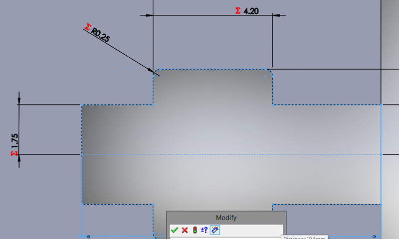
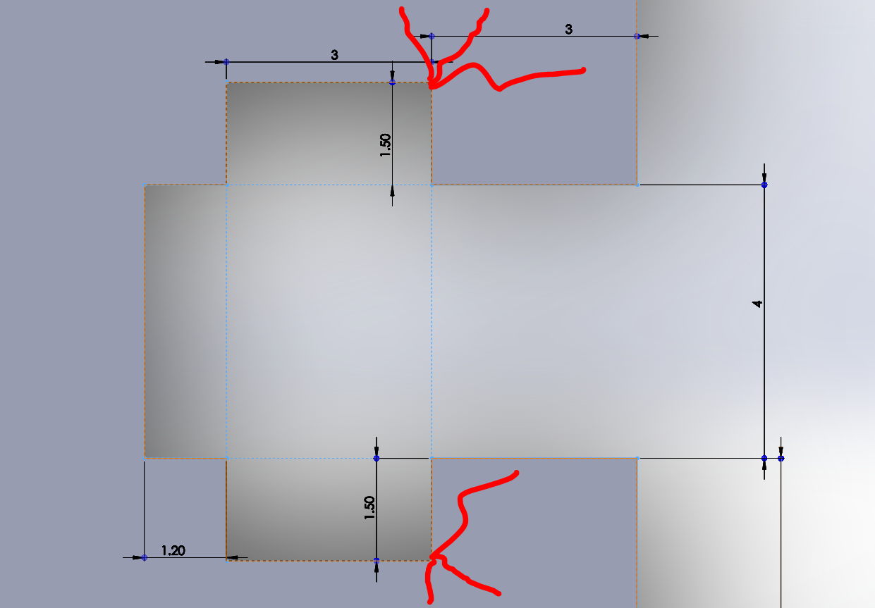
With this in mind, a natural first step is to include fillets in all my T-slots. Easy fix!
Another step I’m taking to avoid problems like this is to kick the frame thickness up a notch – I’ve settled on 10mm thick acrylic for the MK2 design. This is awesome thick – I had trouble finding someone locally who can laser-cut it for me. This should make the frame super-sturdy, and it was already really solid.
Final strategy to avoid putting too much strain on the T-Slots: spring washers. I ended up swapping the MK1 kits to use spring washers instead of regular flat washers (one of the changes I made), and from what I’ve seen it made a positive difference. Spring washers should give the bolt a little bit of give while still keeping things held in place tightly.

CAD Approach
As a student, SolidWorks is the CAD software I’ve been exposed to and taught. I haven’t used it hugely in my studies, but I’ve made huge use of it in my 3D printing related activities. It’s a fantastic tool, the student version is fantastic to have access to.
I don’t know how to use 95% of the stuff SolidWorks is capable of – but I do know how to use enough of it to test out most of my design ideas virtually – which makes things so much easier!
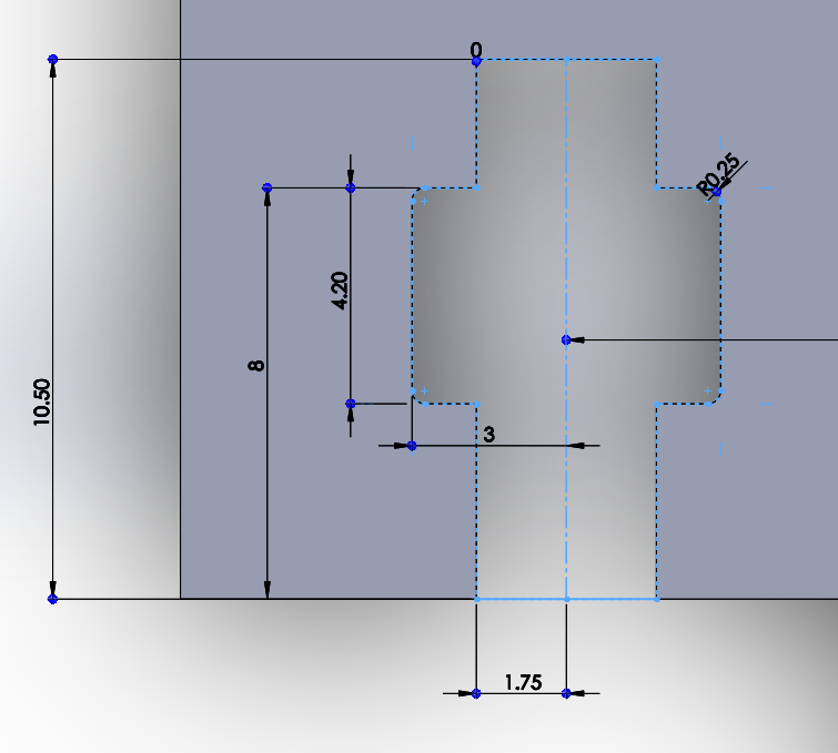
One of the things I was concerned with early on was on how I was going to struggle to rapidly make changes to the design – it felt like the more work I did, the more I had to fix later if I changed my mind on something. Something as simple as the T-slot cut-out above – what if I got through most of the design, then decided I wanted the slots to be longer – or shorter, or wider, or have a different fillet radius – I don’t want to have to go through and edit every single T-slot by hand. Of course, I don’t think anyone would expect that you would – I’m sure CAD professionals deal with this stuff all the time, and know how to only do the work once. Unfortunately this wasn’t something I’d dealt with before, so I had to do some research.
My first thought came from my (still limited, but > CAD) programming knowledge. Surely there must be a way to set these dimensions up as global variables? Then I could just change the numbers once and have the entire design change?
Yes. SolidWorks does this. It’s easy and really well integrated, and I’d never known about it or used it before.
Fantastic, this makes things a lot easier. Still, a printer is made up of a lot of parts, and having a separate set of variables inside each file / part would still lead to a lot of repetition. Surely there’s some way to share variables across different files?
Yes. SolidWorks does this. It’s easy and really well integrated, and I’d never known about it or used it before. AGAIN.
Going through the ‘Equations’ tool:
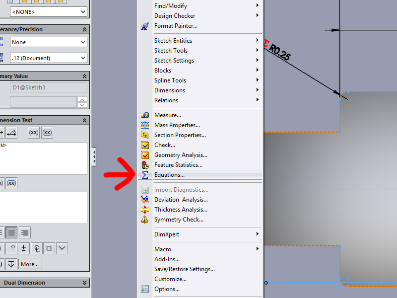
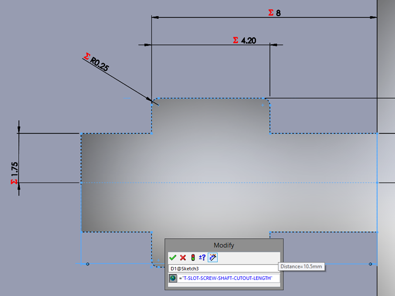
There’s the option to export all your variables to an external text file, and there’s the option to import all variables from a text file – great start. Most importantly – ta da – there’s the option to link the imported variables to the text file!

Yep, that’s fantastically helpful. Suddenly, I can edit a text file, hit rebuild (CTRL+B) and the changes take effect.
Even better, rebuilding any level above the part (i.e. rebuilding the printer assembly made up of all the different parts) will cause each individual part to rebuild – so I can change the text file, hit rebuild and watch the whole printer change.
Further, not only can you set variables in the text file – you can build equations using these variables. This is really handy, as you can pretty quickly build up some useful behaviour from a bunch of simple equations.
Naturally, I went a little crazy with things – at this point nearly 100% of my printer design is driven by variables. This makes it really easy to test out different ideas. I’ll add some examples below when I’ve got more to show.
EDIT: As promised, here’s an example of this in action with the first prototype-ready design (spoilers for future posts!):
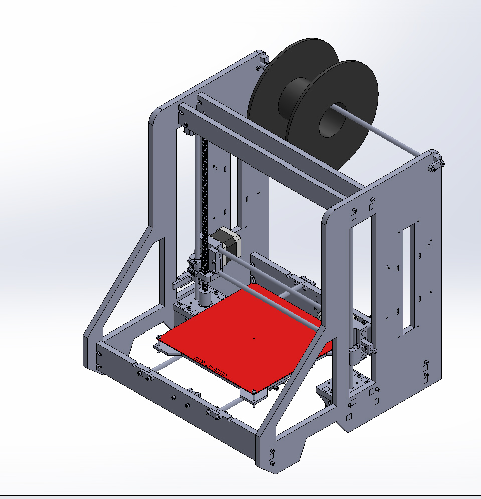

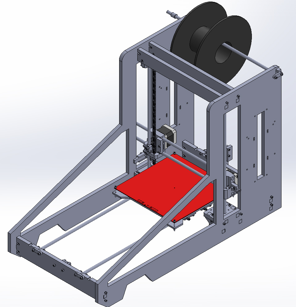
Although a Y-axis that long probably isn’t too helpful, this shows how powerful these linked variables can be. I only had to change two numbers in a text file to get these results – so far this is making testing different ideas really easy and fast, which is awesome.
Leave a Reply