One of the problems I’ve encountered in the past when using RAMPS electronics to control a dual-extruder printer is the lack of sufficient fan support. Dual extruder setups can require a few fans, usually one controlled fan (for cooling the print) and one or two always-on fans for cooling the hotends. Adding a second hotend takes up the 12V MOSFET usually used for running a controlled fan, leaving no option but to solder directly to the 12V lines on the board – which removes any control over these fans.
If your printer has an always-on power supply (like a regular LED-style power supply as found on most printers) then these fans are going to be running 24-7 unless you manually switch off the power. I had to deal with this for a few days while testing the MK2 printer, and I decided to play around with the problem and see what solutions there are.
To be fair, there are already a few solutions out there to address this problem. These typically give you connections for an extra fan or two, usually connected to digital pins on the RAMPS board so the fans can be controlled through the printer’s firmware. These are good solutions, and are definitely something I want to investigate. However, I had another idea I wanted to play with first.
The first thing I wanted to try was to set up fans that would turn on and off automatically, depending on if the printer is running – without requiring any communication with the RAMPS board (or at least, no modifications to the firmware on the printer).
The purpose of these fans would be to cool one or more hotends – preferably only when the hotend in question is heated up. This would be handy because it would mean that during single-hotend prints only the required fans are running – prolonging fan life, reducing noise, etc.
My idea was to design a small board that sits over the RAMPS thermistor connections – reading the values but not interfering, so that a small AVR on the fan board can get the temperature of each hotend, and drive connected MOSFETs appropriately.
First thing to check – will this work, and will it interfere with the normal thermistor sampling?

From the look of things in the RAMPS schematic, intercepting the thermistor pins shouldn’t cause any problems. Assuming a direct pass-through, the thermistors will still be connected to the pull-up resistors and decoupling capacitors in exactly the same way – our board should really only look like a slightly longer wire, which shouldn’t have any impact.
So the basic idea should work. The next problem – running these fans is going to require a connection to 12V power somewhere – and there are no auxiliary connections on the RAMPS board anywhere near the thermistors. We could just leave a connection for two wires, and let the user wire the board into 12V somewhere – but I’d rather we get this taken care of in the design.
There is one spot on the board nearby where 12V power is available – the stepper driver sockets. The nearest is the socket for the 5th driver – the one that would typically be the second extruder driver. Perhaps we can tap into the 12V here.
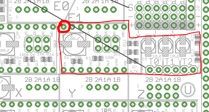
To do this, our board is going to need to sit between the stepper driver and RAMPS. The stepper driver will then sit on top of our expansion board – that could work. This would also give us the space underneath the stepper for board layout, which should come in handy.
So, with these requirements in mind, here’s a prototype schematic:
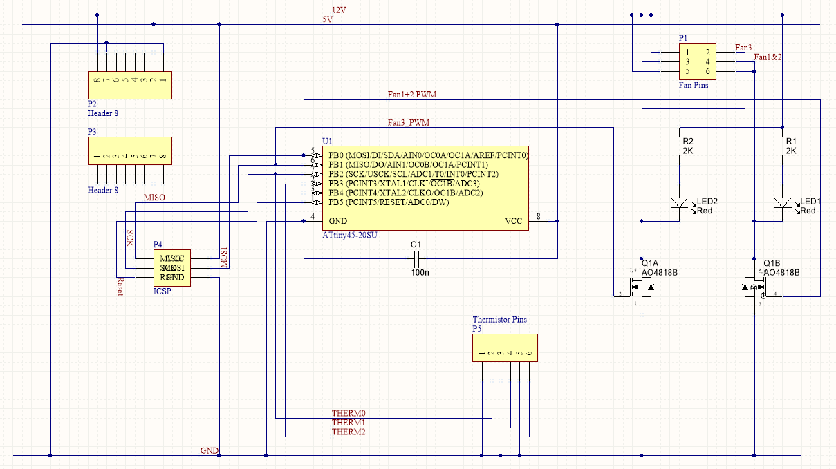
So, what do we have here? Well, there’s an ATtiny (probably a 45) connected up to a dual-channel MOSFET. Each channel of the MOSFET is hooked up to a pin header, so a fan can be plugged directly in. I’ve included connections for three fans even though we only have two controllable channels – the first two fans are driven at the same speed (perhaps one fan for the hotend and one for the electronics?).
There are headers to connect to the RAMPS thermistors / stepper driver pins, and an 3×2 pin header for programming the AVR in system.
Let’s see about getting this to fit in the space we have:
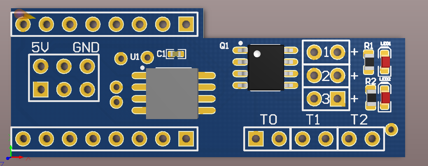
After some very careful measuring of a RAMPS board I have on hand, I had the above board figured out. There’s a bit of room to squeeze things together tighter, but the board needs to take up the space to connect to RAMPS anyway – might as well use it.
I sent the above board off to a fab house a week ago, and today the PCBs arrived:
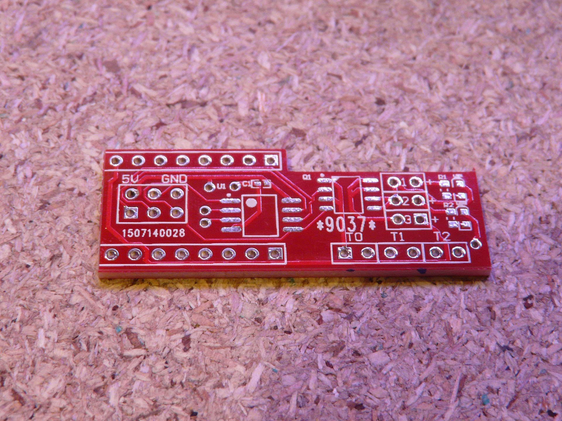
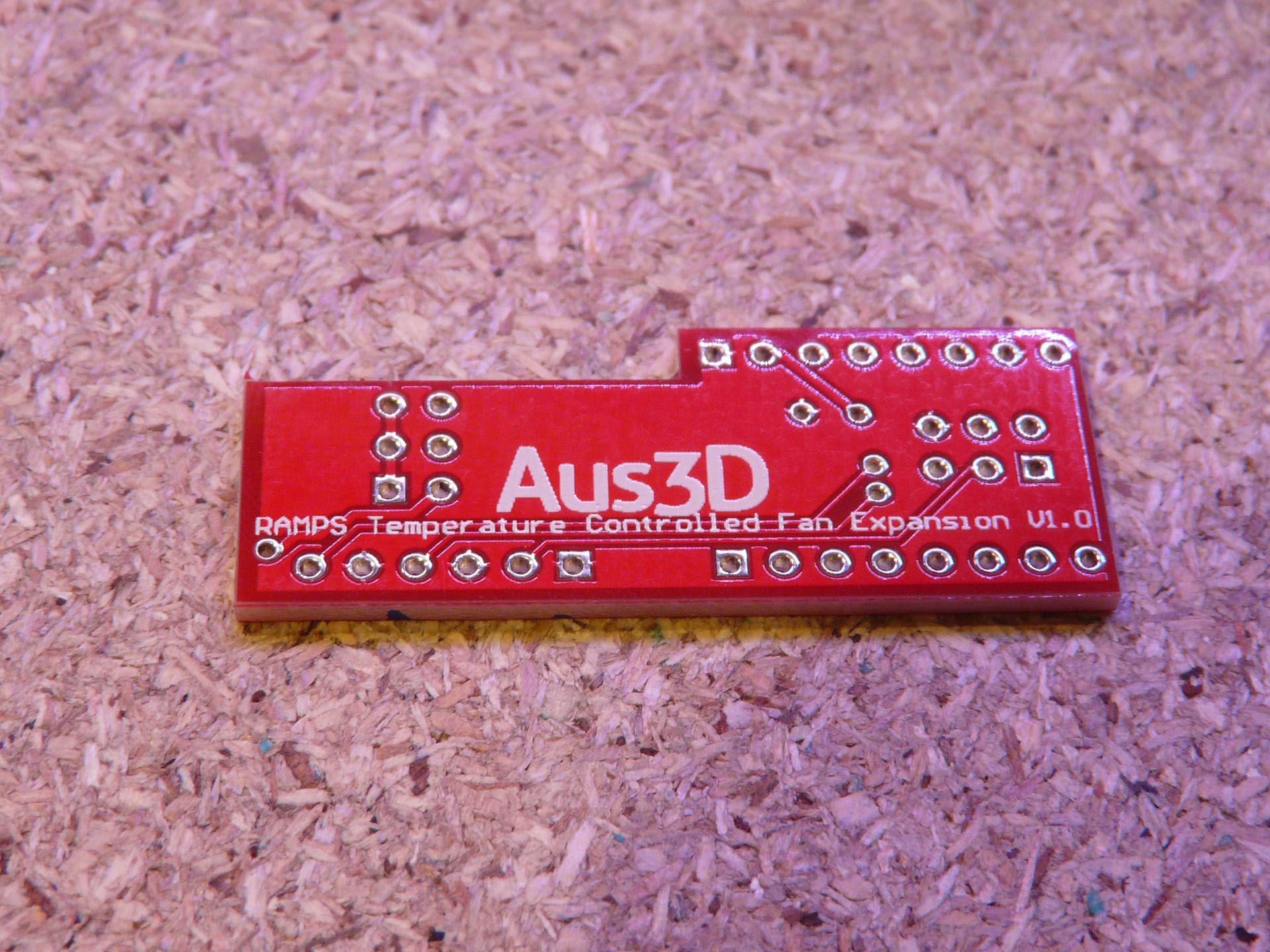
I’m really happy with how they came out – kudos to DirtyPCBs, really fantastic work. All the traces look good, I can’t see any signs of electrical problems. Even the logo on the silkscreen came out really nicely – awesome! Little disappointed I forgot to get them ENIG plated instead of HASL, but for test units that shouldn’t matter. It took 7 days from ordering to arrival – but I did pay for the faster turn-around time. Still, that’s the fastest PCB turn-around I’ve had.
I’m still waiting on the MOSFETs to arrive – Digi-Key, hurry up! Once they come in, I’ll be putting these boards together and seeing if they work as intended. Stay tuned!
Edit: Here’s Part 2 – see how the adventure turns out!
Leave a Reply