I’ve been selling Prusa Mendel i3 kits on Aus3D for a while now. The kits I’ve been selling so far (which I’ll refer to as MK1 kits from here onwards), are fairly decent kits. I didn’t design them, they were designed and manufactured in China – I’ve been buying them in and making a few improvements before shipping them as the Aus3D Prusa Mendel i3 kit. I ended up reverse-engineering CAD files for the frame so I could print / cut replacement parts locally, and I’ve had these files available on GitHub for a while now.
As a business strategy, this approach makes sense. China is good at making stuff, and these kits work pretty well – better than most other Chinese printer kits I’ve tried. As someone trying to run a business, I’ve been happy to attach my business’s name to them.
As an engineer, I know we can be shipping a much better kit.
Unfortunately my supplier for these kits has been pretty intractable about what they will and won’t change – most modifications I end up doing locally myself, and there’s only so much that can be changed from the original design. They refuse to ship kits with any components removed – so I can’t even customise the kits too much without losing money on them.
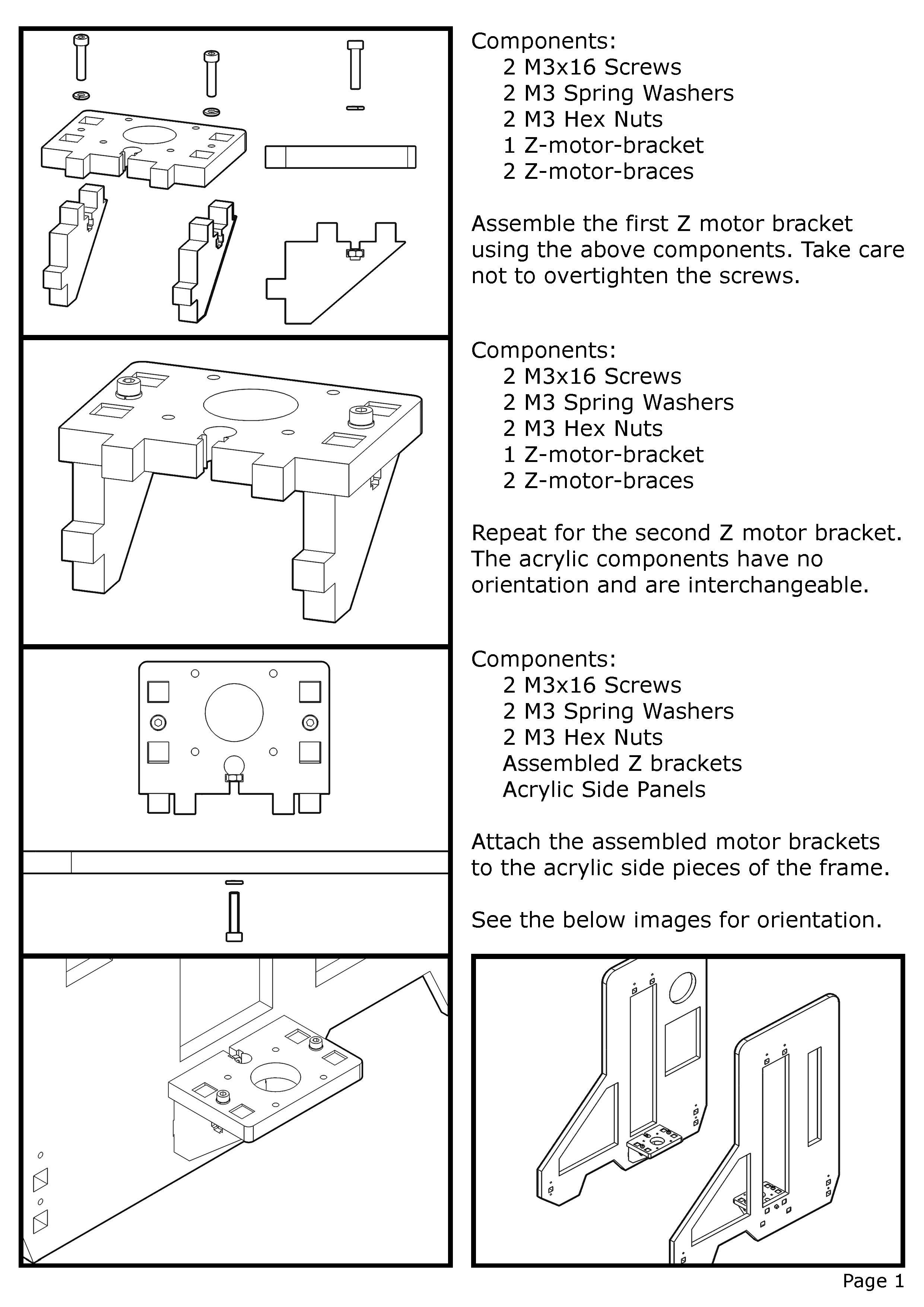
I’ve done a lot to support these kits – I’ve written (and drawn) a full graphical assembly guide, I’ve set up a default firmware that works fairly well, and I’ve modified the printed parts to get the most I can out of the design. They’ve worked well, and I think these improvements have made them a quality kit worth buying.
It’s been an uphill battle though – my supplier will often change or substitute components without telling me, and I usually end up footing the bill for any problems caused by this. It’s been fun, but it’s time for a change.
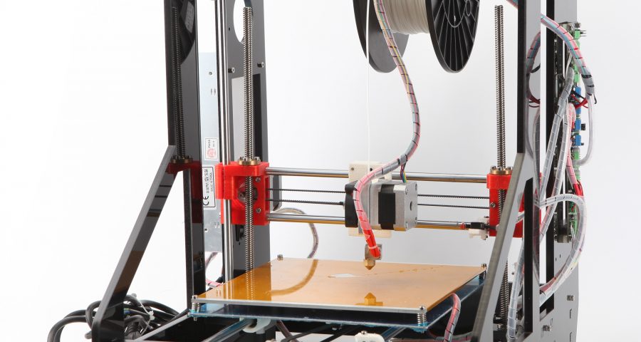
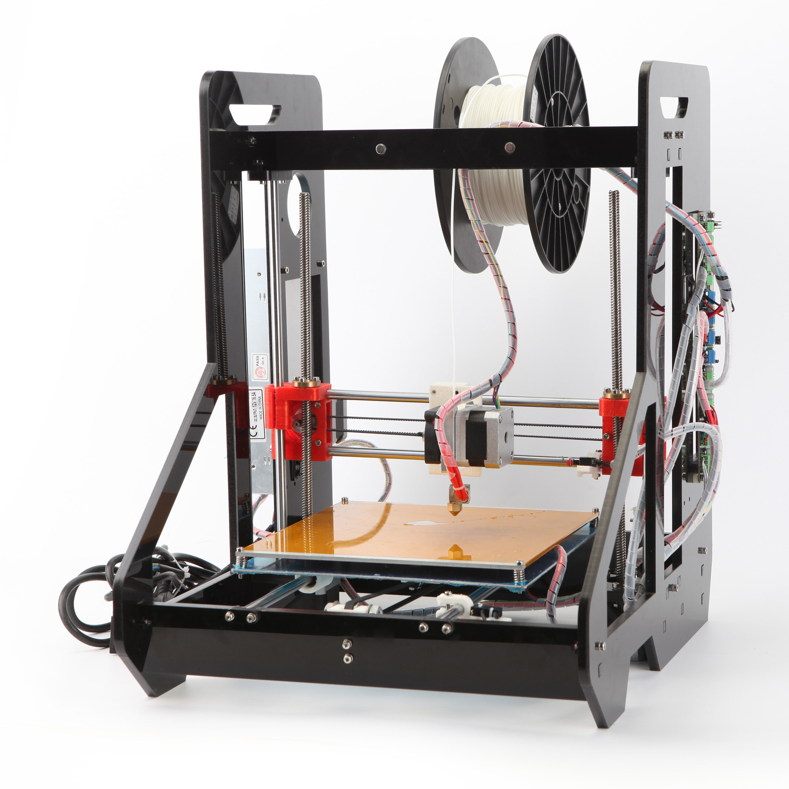
I’ve decided to start from scratch, and do a complete re-design myself. I want to keep in the style of the MK1 kits (because they look cool, and there are a few benefits to the acrylic frame design I really like), but looks aside, this is going to be a completely different printer.
I had several goals in mind when setting out to design the Aus3D MK2. Here are a few of the key things I wanted from the design:
- Full 200x200x200mm build area. The MK1 required a few modifications to achieve this, out of the box it was closer to 150x150x180mm.
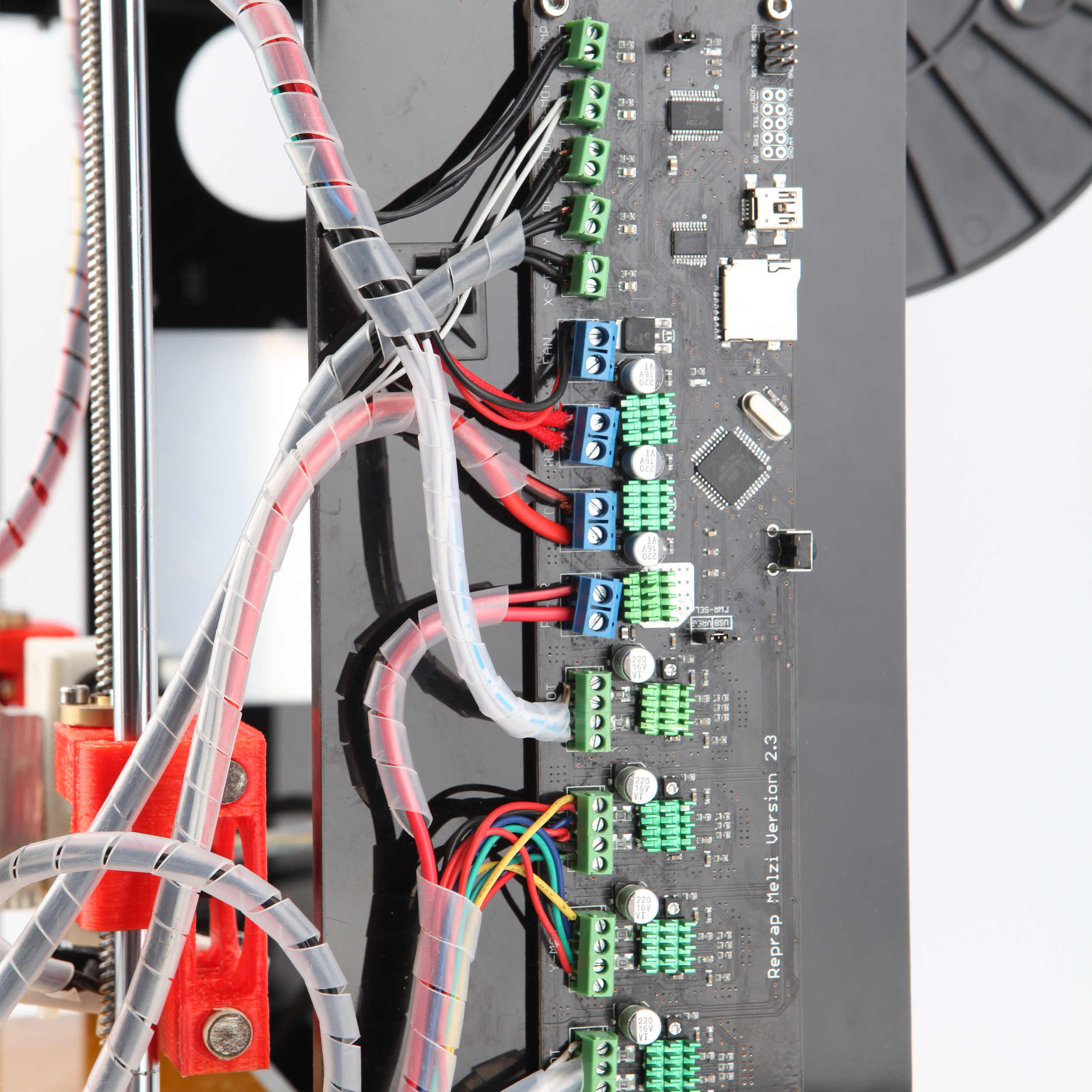
- Support for different control boards. The MK1 frames were designed to suit a Melzi controller only. The Melzi boards are really decent all-in-one controllers, but lots of people want to use RAMPS and ended up having to drill holes. Support for multiple boards would be handy, and I plan on swapping from Melzi to RAMPS in the kits anyway, as RAMPS is much more expandable.
- A better spool holder. The spool holder in the MK1 kits was pretty good – it had one, unlike quite a few kits, and it kept the spool out of the way really nicely. It only holds one spool, though, and swapping spools can be a bit of a pain. While I’ve never seen the spool holder break, looking at it always worries me – the spool acts as a large lever, putting a fair amount of pressure on the frame.
- Automatic bed levelling. The MK1 doesn’t have this, and the X-carriage isn’t easily modifiable to add it in. I’m still not settled on an approach for this, but it’s something I’d really like in the design.
- Better extruder + hot end. The MK1 kits come with an all-in-one extruder, which is a combination of a direct-drive extruder and a J-head / E3D mashup. Annoyingly, the two are integrated into one another and not replaceable, and they’re also matched with the X-carriage. Using a different hotend means printing a new carriage and extruder, something I don’t want people to have to do. For the MK2, I’d like:
- A solid, direct-drive extruder that’s compatible with as many hotends as possible.
- A reliable, quality hotend that can be easily removed (but hopefully no one will want to!)
- An X-Carriage that’s simple, sturdy, and expandable (fans, etc).
Finally, I want to get the frame cut locally – that way I can be sure of the quality, and have fairly quick turn-around if I need to change something.
There are lots of other small things with the design I want to keep in mind – but this is a list of the main things. I’ll post updates as I go through, hopefully I’ll be able to tick off all of the above once the design is finished.
I’ll be keeping the design up on GitHub. I’ve decided to go with a Creative Commons BY-NC-SA license for the time being – others are free to use this design for personal use, to make changes and adapt it and so on – but for the time being I’m restricting commercial use. I feel like a jerk, but Aus3D is still young and someone else walking in and crushing me with my own design would suck. I know lots of people won’t consider this to be fully open source – in my defence, Printrbot used the same license until very recently, and I think they’re now in a position where someone out-manufacturing them at their own design is not a possibility (and I imagine that made their change easier).
Does your design have adjustable X-Axis belt tension with a system that puts the load off the Z-Axis screws and straight rods back onto the X-Axis rods?
Hi Ralph,
Good question! I did play around with different solutions, but the setup I ended up going with is a bit of a compromise between a regular i3 and the modifications that people have made to correct this issue.
There are bolts on both the X-motor and X-idler printed parts that are designed to grip the X rods. Tightening these bolts prevents the distance between the ends of the X axis from shifting, so once these bolts are tightened the belt can be tensioned without exerting a force on the Z leadscrew or smoothrod.
However, because the system is dependent on a bolt gripping a smooth rod, too much tension can cause the bolts to slip and suddenly the force is being exerted on the Z rods / leadscrews. I’ve found that the belt can be tensioned to the point where you can produce an audible twang without the bolts slipping, but if you continue to over-tension the belt eventually things will go badly.
So far, I haven’t had a problem unless I was specifically over-tightening things trying to cause a failure.
Hope that answers your question! Let me know if you have any others, happy to discuss things!
I see, not a bad compromise. I am enjoying the ‘re-engineer the cheap chinese kit’ thing, and it is an issue with my setup, there is nothing apart from plastic on rod friction holding the x-rods and when I tension the GT2 it pulls the Z-screws out of vertical.
Perhaps putting some sort of caps at the end of the x-rods and then clamp the caps with a bolt for better grip.
Also, what do you think about timing belt tension springs? They do seem to stop loose belts, but unless they are fully stretched they do add small oscillations then the head goes around right angles x->y. I’m not sure they are worth it if I can design an adjustable tension system.
Hi Ralph,
Sorry I didn’t reply sooner, missed that last comment!
I hear what you’re saying about the friction-only setup. A lot of i3’s (and other printers too, I suppose) use that setup, and while it works if you get everything correctly tensioned, it’s easy for things to fall out of alignment. I remember when I built my first i3 I had the printed parts made tight enough I needed to hammer the rods in, and once I got the distance correct I put glue where I could to keep them in place. The rods never slipped at any tightness, but I sure wasn’t going to be able to adjust the rods if I needed to.
The caps and bolt idea could be worth exploring, definitely. My experience with tension springs is similar, I’ve only ever tried them once and I felt like they impacted the print quality. Ended up printing a new idler piece rather than deal with them – perhaps there are different or better springs for this now, I’m not sure.