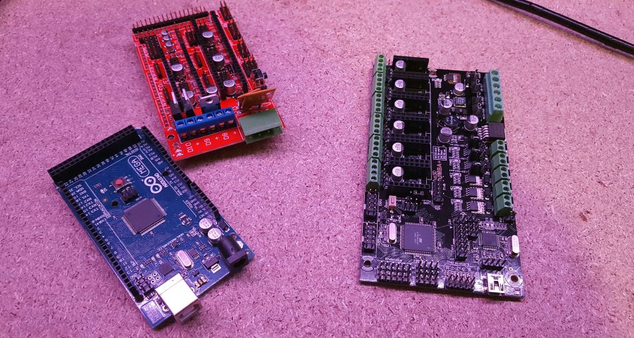
I recently got my hands on a FLIR One thermal camera, and I’d been dying for the opportunity to put it to use. I also recently received the first batch of RUMBA+ boards for testing, and I realised this was the perfect opportunity to test both.
One of my main goals with the RUMBA+ design was to improve the MOSFET side of things so that the board would run nice and cool even under heavy load. Sadly I don’t have a vanilla RUMBA board on hand to test against at the moment, but I do have a bunch of RAMPS 1.4 boards – so I decided to do a comparison between the two.

Methodology
First I had to figure out what I’d be testing, and how I’d go about it. I decided that I’d set both boards up on my desk, with the camera mounted overhead so I could capture both boards side-by-side. I didn’t want to be imaging the boards separately, as I was worried that I’d end up with different temperature-scales in each image and not make for a clear and fair comparison. It turns out this fear was largely unfounded, as I later discovered FLIR’s software allows for adjusting the temperature scale after the fact – still, it makes things nice and easy doing a side-by-side comparison.
I connected each control board up to an E3D Lite6 HotEnd, MK3-Aluminium heated bed, and 12V 20A power supply. This will let me test three MOSFET outputs – a 12V fan, 25W heater cartridge, and ~ 100W heated bed. Both boards were connected to the same laptop for control.

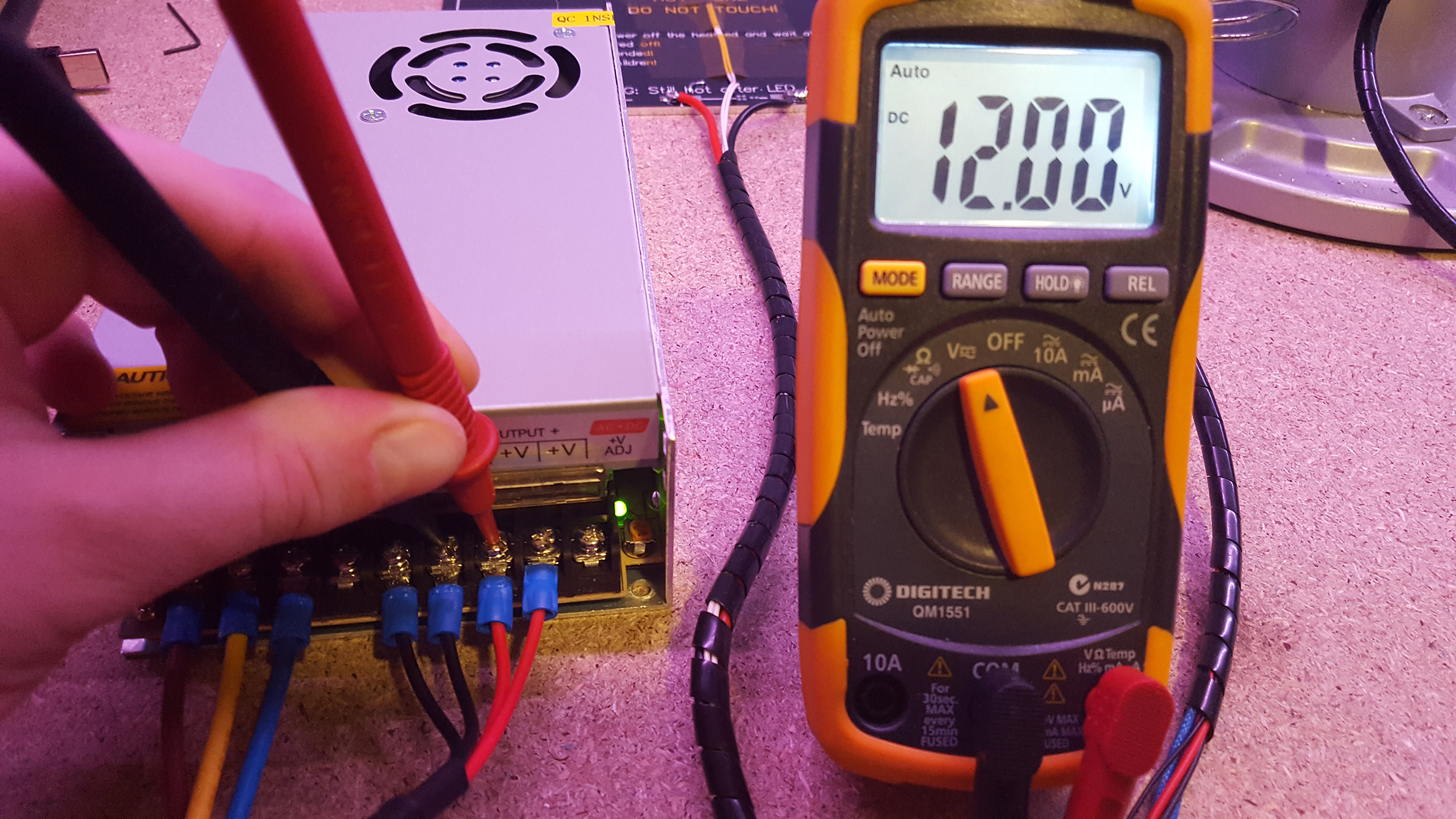
There are a few variables here that need to be accounted for. First off, I checked through the different heated beds I had on hand to find two with very closely matching resistances – it wouldn’t be a fair test if one bed was drawing a lot more power than the other. I also used a multimeter to calibrate the output of both power supplies – I don’t know how accurate my multimeter is, but the important thing here is that the power supplies are consistent.
I decided there were a few things I wanted to check. First off, I thought it would be interesting to see the idle temperature of both boards. I decided I’d classify the idle temperature as the temperature that the boards reached after being powered but inactive for ten minutes.
I also thought it would be interesting to see the impact of running a HotEnd – that’s one MOSFET running to drive the heating element, and another running to drive the cooling fan. Thinking about how I’d measure the impact of driving loads with the MOSFETs, I realised there were two different temperatures I was interested in. While the heating element is attempting to reach temperature, the MOSFET will be running at 100% duty-cycle – to largely misappropriate a term, I’m referring to this as the HotEnd transient temperature. Once the heating element reaches temperature, the duty-cycle will drop – say to 50% – at which point, the MOSFETs temperature will likely drop back down a little. I’m calling this second, lower temperature the HotEnd steady-state temperature. I’d measure the HotEnd transient temperature at the moment the heating element reached the desired temperature (decided to be 210C), and the HotEnd steady-state temperature ten minutes after that.
After testing the HotEnd, I’d then test the heated bed. Because I’m interested in results that approximate real-world applications, I’d keep the HotEnd MOSFETs running during this process. As with the HotEnd, I’m interested in both heated-bed transient and heated-bed steady-state temperatures.
I was also interested in how the boards would perform running at different voltages – the power supplies I’m using can be adjusted from ~10.2 to ~14.9V, and I decided I’d test the upper half of that range – 12.0V to 14.5V in 0.5V increments. That should allow me to plot the temperature response of both boards as voltage increases – after all, it’s not uncommon to run printer power supplies a little on the high side to get more grunt for the heated bed.
Test Results
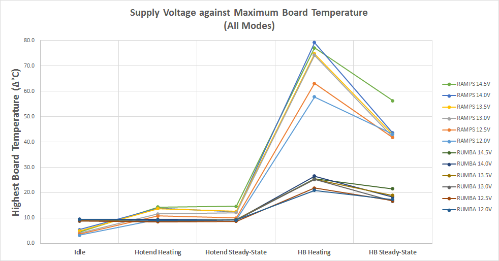
I ran the tests, collected a bunch of thermal images, and extracted the following data from those images:
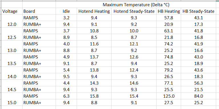
The testing ended up taking longer than I expected – all afternoon and a lot of the evening too, and the ambient temperature dropped a few degrees over that time. To try and combat this all numbers in the above table are the delta T, where the reference temperature is ambient temperature as given in each thermal image – so each reading indicates how much hotter than ambient the board was, and not actual temperature.
Ambient fluctuated between 17 and 22°C, so add ~ 20 to any of the above to get the board’s absolute temperature.
It’s probably reasonable to assume there’s a bit of noise included with each reading – for instance, occasionally RUMBA+ appears to be cooler when running the HotEnd than it was at idle, but this is likely just due to a bit of variance from one reading to the next.
After running all of the tests, I decided to go all out and test again with both power supplies at their maximum of ~ 15V – and I’ve added those results to the above table too.
Analysis of Results
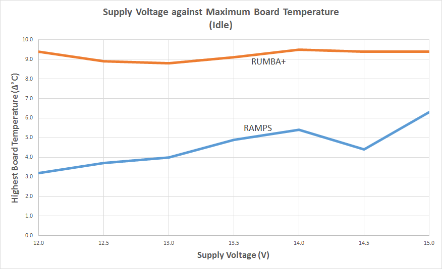
Let’s start at idle and work our way up. When both boards are idle, it appears that RUMBA+ is running slightly warmer. This result makes sense, as at idle the only components that are really doing anything are the ATmega2560, ATmega16u2, and 5V voltage regulator. All of these components are visible on the RUMBA+ board, but are hidden underneath the RAMPS board on the Arduino Mega 2560 – so we can’t see the active components on the RAMPS setup. I’d be interested in doing a comparison with a de-RAMPS’d Arduino Mega to see the difference between the Mega’s linear regulator and RUMBA+’s switching regulator, but I’ll save that for another time (because I’m lazy). Taking a quick look at the idle temperatures at different supply voltages, it does looks like RAMPS’ temperature increases proportionally while RUMBA+’s is fairly constant – which is the behaviour you’d expect from a linear vs switching regulator.
Next up was the HotEnd transient temperature. Here we start to put a bit of power through the MOSFETs, and I thought we’d see a bit of a temperature rise because of it. The results were not as significant as I was expecting, but are still interesting – RAMPS sees a slight temperature rise, which surprisingly actually seems to come mostly from the MOSFET status LEDs, while the MOSFETs themselves don’t heat up significantly.

On the RAMPS board I was testing the LEDs seemed to be paired with fairly low-value resistors, as they were very bright (blinding, really). The temperature rise on the LEDs appears proportional to the input voltage – this makes sense, as the MOSFET status LEDs draw power from the ’12V’ input.
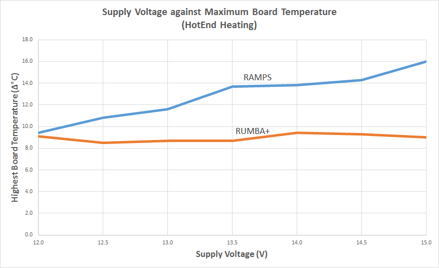
RUMBA+ doesn’t see any discernible temperature rise on either the MOSFETs or the LEDs – on RUMBA+, the status LEDs draw power from the regulated 5V supply, and are paired with resistors that keep them dimmer than the RAMPS LEDs. So on RUMBA+, the LED brightness and power dissipation stays constant as the input voltage varies. Because the temperature rise was so small, there was basically no change between the transient and steady-state temperatures.
Apart from the LEDs, we can also see that the smaller fuse on RAMPS starts to warm up a little, making it the second warmest component on the board. On RUMBA+, the ATmega2560 is still the warmest component (at the same temperature as at idle), with the 5V regulator and ATmega16u2 trailing behind.
At the end of the day, none of this is a big deal – we’re only talking a temperature rise of a few degrees above idle on RAMPS, which is hardly something that’s going to have an impact on the board’s performance. It’s interesting to see where the power dissipation is though, and that it’s not necessarily where I thought it would be (MOSFET).
Next up was running the heated bed. This is where I was expecting to see a big temperature rise – I know I’ve had trouble with RAMPS boards getting too hot before, and I was curious to see if I’d have similar problems now that I had a board in the spotlight.
Starting at 12V, it’s clear straight away that both boards begin to heat up pretty quickly here.
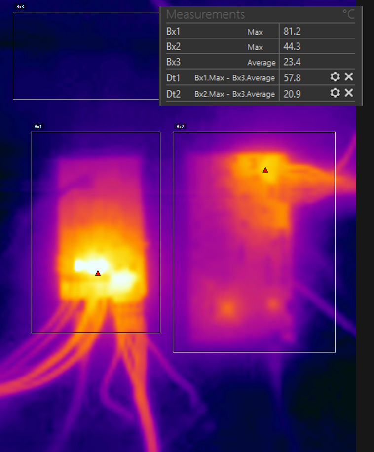
On RAMPS the heated-bed MOSFET and larger PTC fuse both start to heat up quickly. The heat diffuses through the PCB quite decently and keeps those components running well under load. However, they’re both through-hole components, and the MOSFET doesn’t have the same capacity to sink heat into the PCB as the SMD MOSFET on RUMBA+ does.
The MOSFET on RUMBA+ has a much lower on-state resistance, and this means it’s generating a lot less heat right out of the gate – which gives RUMBA+ a handy advantage here. The heat that is being generated spreads to the planes in the PCB very quickly through the SMD component’s large contact area and results in the board heating at almost the same rate as the MOSFET itself. The thermal software identifies a section of the PCB as the hottest part of the RUMBA+ board, and not the MOSFET as I’d have expected – perhaps there’s a narrow trace on the PCB dissipating more heat than the MOSFET is.
At 12V, RUMBA+ reached 21°C above ambient, while RAMPS reached 58°C above ambient. As the supply voltage increased, so did the temperature of both boards:

From 13.5V onward, the MOSFET on RAMPS reached temperatures of 75°C+ above ambient – putting that component around the 100°C mark. This is well within what the component and board can handle, but you’d want to take care not to touch it.
RUMBA+ stays at comfortable touching-temperatures – not that you’d really want to touch either control board while it’s running high-power loads – there’s electricity there, after all!
This section – the heated-bed transient – was the most stressful part of the test. Once the heated-beds had reached temperature, the MOSFETs – and surrounding board – were able to cool back down a few degrees. This can be seen in the following plot:
Both boards are able to cool back down once the heated-bed is at temperature. If any of the boards’ components were going to fail for temperature-related reasons, it would likely be during this heat-up period.
Pushing to Failure
Initially, I only tested up to 14.5V, as both power supplies seemed to max-out at roughly 14.9V and I figured I’d stick to my nice 0.5V increments. However, I eventually decided to run another set of tests with both supplies set to this maximum. You may ask why I did this – honestly, I did it because I’d had a RAMPS board burn up on me before, and I was feeling a little cheated that I hadn’t got to see this with my new thermal camera. It’s that sort of feeling you get when you take a faulty item back to the store, and suddenly it works perfectly when you’re there – I wanted to see a failure mode. The RAMPS board under test had actually surpassed my expectations, and I was impressed with how hardy it had been thus far.
Both power supplies were tweaked to their maximum ~ 14.9V, and I ran through the set of tests. Idle and HotEnd temperatures were pretty standard – they’re in the results table above, and the general trends continued in expected and un-exciting ways.
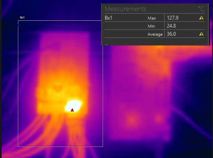
Once I started the heated-beds, however, things became exciting. At first, all proceeded as normal – the heated-bed transient test usually took > 5 minutes to run, the time it took for the heated-bed to reach temperature. As mentioned earlier, RAMPS was reaching roughly 100°C here. This time the MOSFET reached that mark and continued to climb. The heated bed was almost at temperature, and relief for the MOSFET nearly in sight – but it had taken all it could take and it couldn’t take no more, and all of a sudden the magic blue smoke escaped.
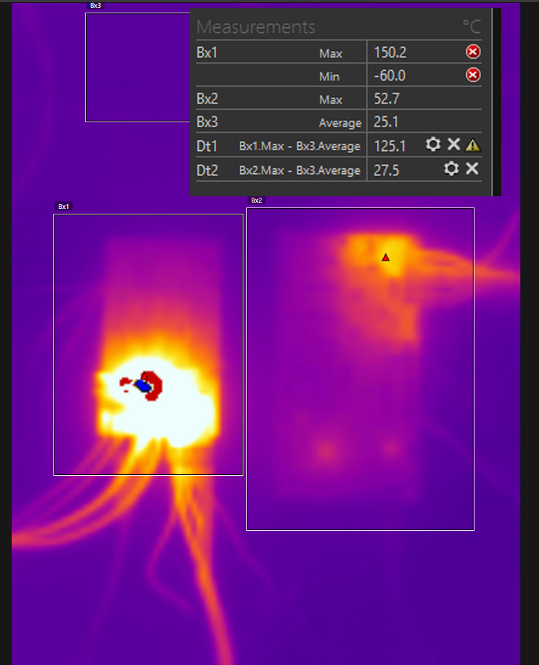
I’m not sure what temperature the MOSFET actually reached – the thermal camera maxed out around 150°C – at which point, the reading seems to overflow to -60°C (that or MOSFETs are very cold on the inside).
After the MOSFET failed, the fuse dedicated to that MOSFET / heated-bed started to heat up. This surprised me, as I expected that the MOSFET would fail-open and that there would be no power flowing through the fuse – failing-open had been (perhaps luckily) my previous experiences with MOSFETs. Clearly I was mistaken, as there was certainly some power flowing through the fuse.
I left the board alone for five minutes at this point, and the temperature stayed pretty much put – so at that point I switched the power off.
Reflection
It’s really unfair to do a comparison between the two boards – RAMPS has been built down to the absolute lowest cost, both as part of the original design and by the subsequent mass-production by Chinese suppliers, and the included MOSFETs reflect that. Adding heat-sinks to the TO220 packages, or swapping the MOSFETs out to something more efficient, would likely make for a fairer comparison – perhaps that’s something I’ll explore another time.
RUMBA+ costs a lot more than a RAMPS board, and you’d expect the performance to be a lot better for that extra cost. With RUMBA+, if anything, I’ve over-spec’d the MOSFETs – they’re way more efficient than they need to be, and I might have been better off going with a cheaper (but still good) option and getting the boards to a lower price-point. When I picked the parts I wasn’t sure how much overhead there would be – I was being cautious, perhaps more than was necessary. Still, I’m relieved to see how well RUMBA+ performs – while they may be a little over-the-top, the MOSFETs are clearly doing a pretty fantastic job of not getting hot. I’ll need to run more intensive tests to be sure, but I’d expect that the screw terminals (rated at 15A) or the PCB (rated similarly) would fail before the MOSFETs themselves.
I’d be interested in doing comparisons against other, more capable control boards – if anyone has a board they’d like to suggest (or send me, for destructive testing purposes only of course…) then make a suggestion in the comments below and I’ll take it on board.
Good effort, very persistent! The first thing I did to my cheapie RAMPS board was install extended copper heatsinks on the mosfets and fan cooling 🙂 So far so good, but I am only driving the heat bed up to 67C for PLA, not 100C+ for ABS so far. Where the RAMPS setups have a real weakness is in their interconnect to the mega board and lots of aux connectors — wiring reliability. I also expect there is a good deal of variability in manufacturing.
Very nice work. Did you also collect hotend and heat bed heat up times for each of the tests? Just curious if the times were different between the ramps and rumba+ and how much the times decreased with increasing voltage.