Background
I’ve been working on an encoder-driven system for error correction for a few months now. Ideally, the end-game would be complete closed-loop control over each axis. This would allow smaller motors (perhaps not even stepper motors), higher accelerations, and the ability to overcome most skipped-step related issues.
I posted a video last month, and after a much-appreciated post by Hackaday there was quite a bit of interest – so this is a follow-up post about the project.

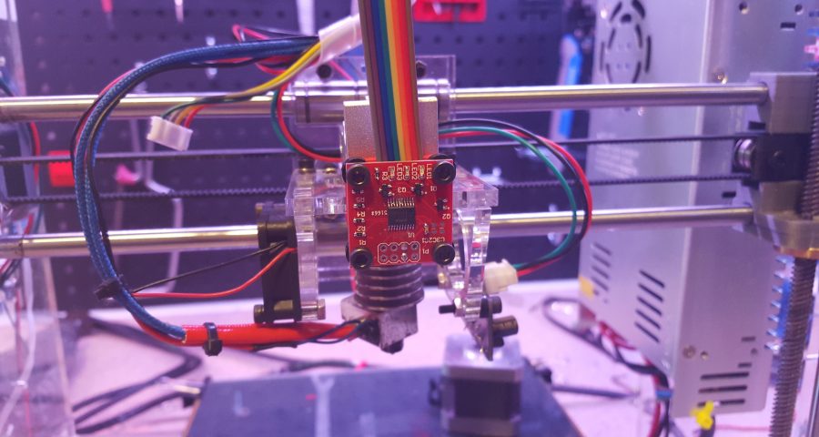
The module itself has a few main components – there’s a magnetic encoder IC, a microcontroller, and two RGB status LEDs.
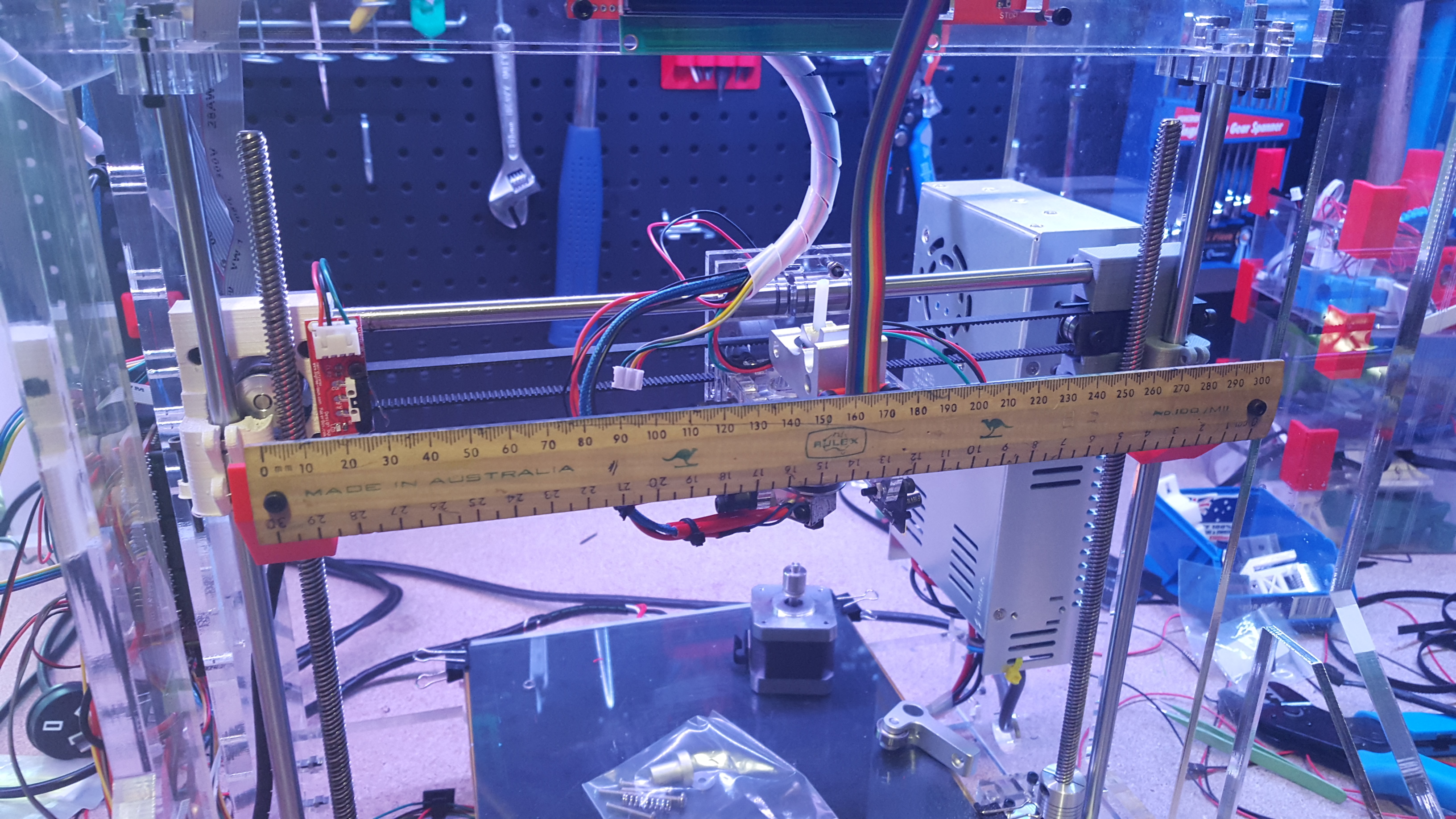
The encoder IC is the core of the project, and also the most expensive component. It uses a magnetic strip (optionally mounted to a ruler for bonus style points) to track its position within a single magnetic pole-pair (the strip is made up of alternating magnetic poles, NSNSNSNS…, one pole per mm). When it moves from one pole-pair (2mm distance) to the next, the distance count loops back around. The microcontroller is there to keep track of the encoder’s position across pole-pairs so that we can track travel across the entire magnetic strip.
The status LEDs indicate whether the magnetic strip is close enough to the encoder, and provide green/yellow/red range indication – which makes tuning things fairly straightforward. The LEDs can also be independently reconfigured over I2C if they’re not needed for status – I’ve taken to using one as a general-purpose illumination LED, and it does a decent job in the absence of anything else.

A small JST-SH connector is used to connect power and I2C lines between the module and the control board. This means the cable is cross-compatible with the cables used in my V1.4 IR Z probes, so I’ve already got plenty of suitable cables on hand – and with this setup, the encoder module plugs directly into the I2C header on RAMPS. With more than one encoder some sort of splitter will be necessary, but I should hopefully have something figured out for that soon.

Recent Progress
Encoder IC Discontinued
Unfortunately, AMS recently discontinued the AS5311 magnetic encoder ICs I’d been using – so I’ve had to switch over to their NSE5310 encoders. They’re very similar – I believe they’re intended as a direct successor – but there are a few differences.
Instead of an SSI interface, they communicate over I2C. At first glance, this was a good thing – I2C should be easier to work with and potentially more robust, but after working out a few more of the details this turned out to be more problematic than I first thought.
The original encoder modules I designed use an AVR to read the output from the encoder, track the position along the axis, and then report this position on demand to the printer control board via I2C. With the new encoder ICs using I2C for communication, my first hope was that I could drop the AVR altogether and make things simpler. Unfortunately, the NSE5310 only supports two different I2C addresses (so far as I can see anyway – feel free to correct me), which means that you’d only be able to have two connected to the printer control board. This might be workable – error correction on only the X and Y axes might be enough for a lot of situations – but it wouldn’t really be ideal going forward.
Additionally, the encoder itself still only tracks the position within the current magnetic pole-pair – in this setup, that’s within 2mm. This means that the printer control board would need to sample each encoder at least once per mm travelled so that the direction of travel can be correctly determined (something something aliasing, something something Nyquist rate). This isn’t unreasonable at first blush, but considering an axis might be moving at speeds over 150mm/s and we might have as many as four encoders in play, that’s a sampling rate of > 600Hz – on top of everything else the control board is already doing. With the newer 32bit control boards this is probably quite doable, but I’d be surprised if there was room to comfortably do this in say Marlin running on an 8bit microcontroller. The goal here is to make adoption as easy as possible, and I certainly don’t want to exclude one of the largest firmware & electronics combinations out there.
So for the time being, the microcontroller on board the encoder PCB stays. The next challenge then is that I now needed the AVR to operate two I2C channels – one as a slave to the main control board, and another as master to the encoder IC.
The ATmega328P I’m using in the encoder boards only has one hardware I2C interface – so it was clear I’d need to do some sort of software-based I2C on another set of pins. I could go with an AVR that has multiple I2C peripherals, but that would increase the cost – better to try in software first. I decided to keep the slave-functionality on the hardware-based channel, as it seemed that the hardware I2C would give me the best chances of remaining compatible with as of yet unknown control boards – provided the I2C spec is adhered to things should work. The software I2C has the potential to be less strictly compliant with timing standards, pin current sink/source etc., so if that interface is used to communicate with the encoder IC – a known, unchanging target – the chances of things breaking in future should be minimised.
The next challenges were finding a way of doing both software and hardware I2C at the same time, and getting the software I2C to run fast enough for this all to be worthwhile. I tried a few different software I2C libraries – most of which were much slower than I was hoping, and a few didn’t like the hardware I2C running at the same time – though perhaps that was a fault on my end. Eventually, I came across the fairly recent SoftwareWire library, which looks to be built upon several earlier libraries. It seems happy running at the same time as the hardware I2C, and at speeds high enough to get things running smoothly.
New Modules
With those changes made, I was ready to test out the new boards – by this point, the new boards had arrived, and I was eager to get going.


The boards arrived looking good – I’d hoped this design was ready for manufacture & release, but unfortunately, that wasn’t the case quite yet. After a few hours of trying to get the modules working, I realised a pretty stupid mistake I’d made – when I swapped the SSI lines over to I2C, I hadn’t added any pull-up resistors. I quickly kludged in some through-hole resistors where I could, and things started working – problem solved, but I’ll need to get another batch of boards made up. Well, I’ve got plenty of spares to test with now anyway!

I spent some time testing the new modules. I had a few concerns about the new encoder ICs – I thought perhaps the I2C interface would be slower than the previous SSI interface (I’m transferring 5 bytes now instead of 3, and perhaps there’s more overhead too), which could cause tracking to fail at high speeds. I’d tested the previous modules to work up to ~ 350mm/s and fail at > 370mm/s. Trying out the new module, it seemed to hold at similar speeds, but I’ve only done a few quick tests. I did clean up the firmware a little to try and speed things up slightly – so hopefully that’s helping out here too. This is also near the maximum speed I can achieve on my test axis, so I can’t push things much further. I need to do a proper long-term test at some point, just to make sure things are stable – but I’ve done a few prints lasting > 5 hours with the new module in place and running, and so far I haven’t seen a problem – so that’s good news.
Another bit of good news – the noise level on these new modules seems to be better than on the previous boards. Before I was seeing roughly ± 25µm noise, with the new boards this looks to be < ± 5µm. It’s likely that this could be a property of the new encoder IC, but I think I can take part of the blame for the previous noise level. I noticed one of my capacitors on the previous board was placed poorly, and corrected that – I don’t know which change made the difference, but overall it’s working better so that’s definitely a plus.
With 1/16th microstepping, a 200 steps/rev stepper and a 20-tooth GT2 pulley, a single microstep on my X axis corresponds to 12.5µm of travel – so it’s likely that the current noise-floor is below a single microstep. Obviously, this says nothing about accuracy or repeatability, but it’s certainly promising.
What’s Next
I’ve added the pull-up resistors to the board and made a few other minor corrections, and the new boards are being made up. It will probably be another few weeks until I’ve got them for testing – but provided things go well I’d like to start getting these modules out there for people to play with.
When they’re ready I’ll have them available for sale on the Aus3D website, and I’ll also do up some documentation on getting up and running with Marlin / RAMPS. I’m keen to try out other control boards and firmware, but for the time being that’s what I’m working with. Anyone who wants to have a go implementing error correction in other firmware (or improving my Marlin code) should definitely give it a shot – my code so far is basic and pretty ugly, but it’s a start – so don’t be afraid to have a go.
This is a very interesting project.
I would love to add an error correction option to my printers.
I hope to see these boards available for sale soon.
I also hope that you will make a good instructions how to modify existing Marlin firmware to make it work with your boards.
Thanks for the comment! Glad to hear you find the project interesting.
I’m still working on bringing these modules out. Right after I wrote this post one of the core components went out of stock pretty much everywhere, but they’re starting to become available again now so things are getting back on track.
During this time I’ve been working on an updated design, which should be more powerful and a bit easier to use – so while the delay has been annoying, hopefully it’s been worth the wait.
Thanks for the points about instructions – I’ll be sure to write up as much info as I can, and I’ll have a modified copy of Marlin up on Github where the changes can be seen for anyone to download.
Sounds good Chris, hope you can keep me in mind when it is available. Cheers Ernie
Great work. Any idea when the Linear Encoder and Z-probe IR modules will be back in stock?