I’m almost at the point where I need to lock the design down and start kitting things for the December launch – a pretty daunting prospect, I must say.
Before I finalise things, there’s one last idea for an improvement that I’ve been thinking about for a while – and it has to do with power input.
Currently the Mark2’s power supply connects to mains by wiring a bare-ended cable into the screw terminals on the power supply. This works fine, and is what a lot of printer builders / kits do.
There are a few disadvantages though:
- Power cable isn’t easily removable
- Difficult to pack up and move printer
- Potential electrical / tripping hazard – hard-wired cable will pull printer with it, or potentially come out of PSU terminal and short on something.
- No option to switch power on / off except at wall socket
- Potentially hard to reach in emergency / hurry
There are other ways people can get around these problems – use a mains cable or power-board with a built-in switch, wire things carefully, use cable ties to provide strain-relief to cables – and so on.
But I’d really like it if the default design mitigated a lot of these problems.
Ideally, it would be nice if the printer had a power socket – something common, like an IEC cable (kettle plug), commonly used in desktop computers among other things.

I spent a bit of time searching for a suitable way to pair such a cable with the printer design in an easily-installable way, and eventually I came across these handy panel-mount sockets:

This seems to tick the boxes – makes it easy to plug / unplug mains power, easy to switch it on and off, and it provides a fuse holder for an M205 fuse – a common size that it should be easy to find a suitable value fuse in.
The back-side of the panel seems to use spade terminals – I can’t quite see what size they are, so I’ll have to do a bit of investigation to see how everything connects together. I’ve ordered a few of these panels so I can start testing ASAP – not a lot of time left, after all!
Before I can get it installed, I need to modify the frame design to suit these panel-mount sockets. Fortunately, I was lucky enough to find someone else has already made a CAD model of such a socket and shared it via GrabCAD – whether or not it’s identical to the units I’ve found is hard to say, but hopefully it’s close enough that things approximately line up.
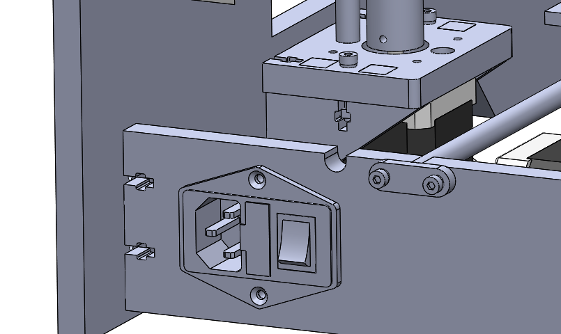
After a little bit of fiddling in SolidWorks, the panel was integrated:

The panel fits on the rear of the printer quite nicely. It’s out of the way, but still fairly easy to access.
I’ll be waiting two or three weeks for the panel connectors to arrive – I’ll likely get another prototype frame cut in that time, so I should be ready to test the connector by the time it arrives.
Overall, it’s an increase to what it will cost to kit a printer, both in parts and in cutting time – but I think the panel connector makes for a neater and safer printer.
Leave a Reply