One hobby that I can’t afford leads into another…
I’ve been printing a lot of stuff lately – and when I came across a 3D printed quadcopter design on Thingiverse, I had to give it a try.
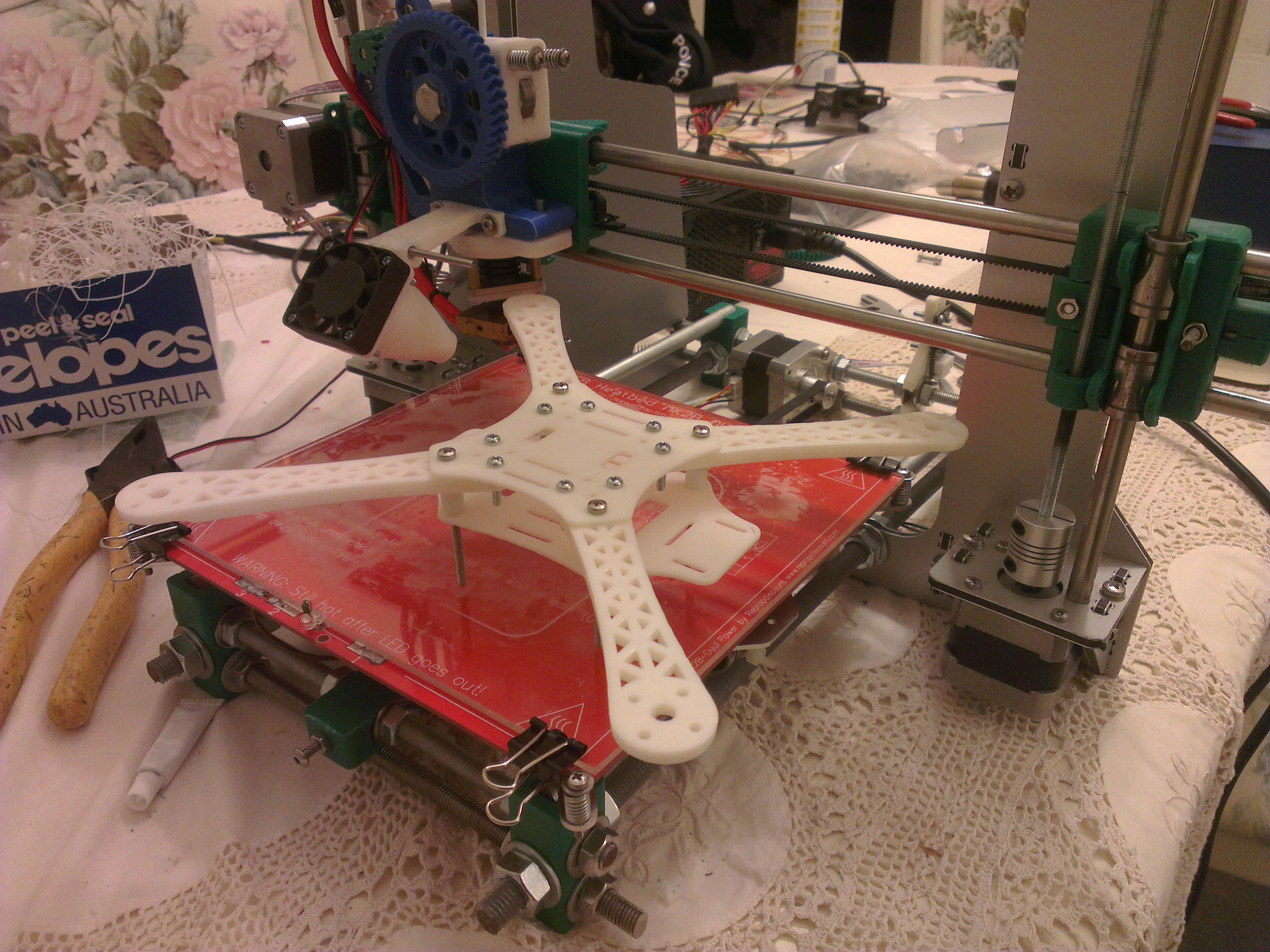
At first, I was only interested in printing the frame to see how it would come out – and I think it came out quite well – but once that was done, I was hooked on the idea of taking the build through to completion and having a working quadcopter.
It didn’t hurt that one of my friends at Uni had been into all-things multirotor for years, so I had at hand a near limitless well of knowledge to point (or at times push) me in the right direction.
After some time spent researching what goes into a quadcopter build, I thought I had a decent idea of what I needed – so I put in an order with HobbyKing for a whole bunch of parts.
I needed to buy a lot! Not only parts directly for the quadcopter, but also a transmitter, batteries, a battery charger – ouch!
The core parts for the quadcopter included:
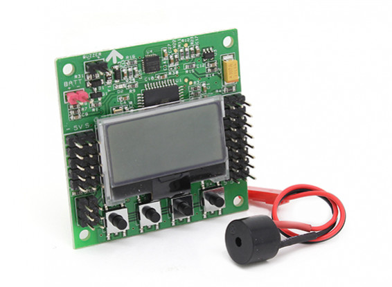
- 1 x KK2.1.5 Multi-rotor LCD Flight Control Board With 6050MPU And Atmel 644PA
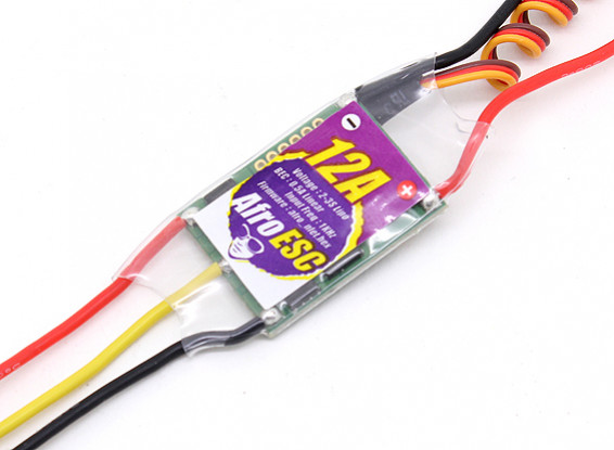
- 4 x Afro ESC 12Amp Lite Multi-rotor Motor Speed Controller (SimonK Firmware) Version II
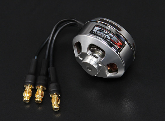
- 4 x Turnigy Aerodrive SK3 2822-1275 Brushless Outrunner Motors
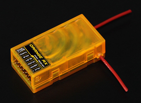
- 1 x OrangeRx R615 Spektrum/JR DSM2 Compatible 6Ch 2.4Ghz Receiver
The transmitter setup:
- 1 x Turnigy 9XR Transmitter Mode 2
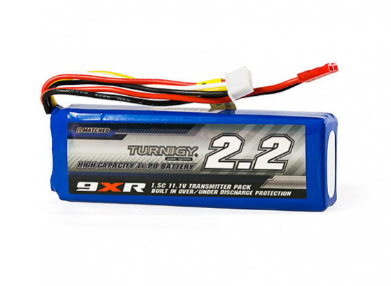
- 1 x Turnigy 9XR Safety Protected 11.1v (3s) 2200mAh 1.5C Transmitter Pack
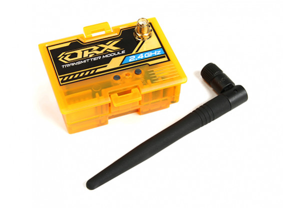
- 1 x OrangeRX DSMX/DSM2 2.4Ghz Transmitter Module (JR/Turnigy compatible)

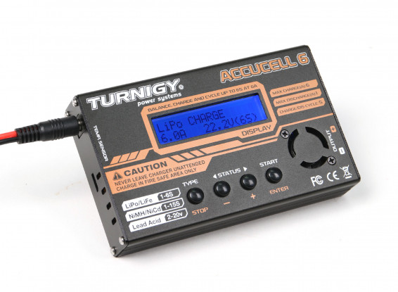
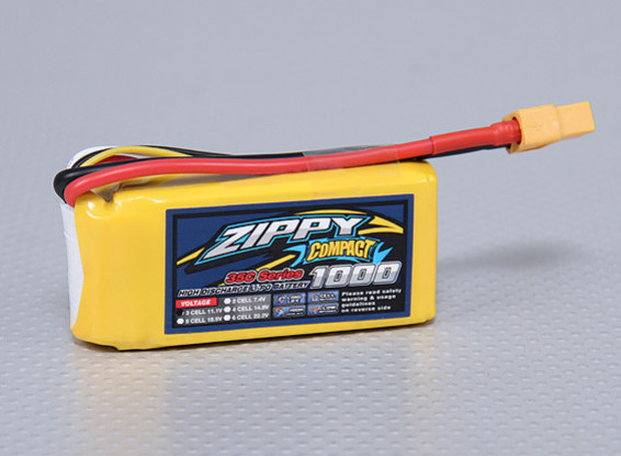
Batteries and charger:
I also ordered quite a lot of differently gauged wire, connectors to suit the motors, ESCs and batteries, velcro, cable ties, nuts and bolts, along with a dozen different sets of propellers around the size I thought I would need.
Unfortunately, I was quite a bit off on that last one – all the propellers I ordered were too small!
My mistake was in thinking that the numbers given for size – whether in inches or millimetres – correspond to the radius of the propellers. I was mistaken; they’re measured by diameter – so everything I bought was half the size I expected.

This should have been an easy thing to pick up on when I was doing my research, and I’m not sure where my idea that the radius was used came from – but it caused a bit of an anti-climactic delay while I had to find a solution.
Novice mistake number one: not understanding propeller dimensions.
Still, I was hopeful there was a way to make them work – I’d ordered a range of sizes, including ones a little larger than I thought I’d
Anyway, I had to build the quadcopter regardless of whether or not these propellers would do the job – so I started putting everything together.
Most of the work that needed to be done was wiring, and there was a fair bit of soldering in that. There are three wires between each ESC and its associated motor. Helpfully, both sets of wires came with bullet-style connectors already installed. Unhelpfully, they were different sizes – 2mm on the ESCs, and 3.5mm on the motors – so I removed the connectors on the ESCs, and soldered on 3.5mm ones to match the motors.
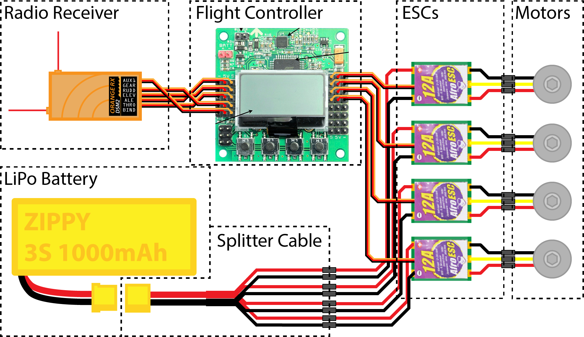
The rest of the wiring was mostly plug-and-play. For the sake of simplicity, I kept existing connectors in use wherever possible, and added connectors to other things that probably could have just been hardwired. I could have saved a bit of weight and clutter by shortening cables and soldering everything in place – but since I wasn’t certain I had done everything
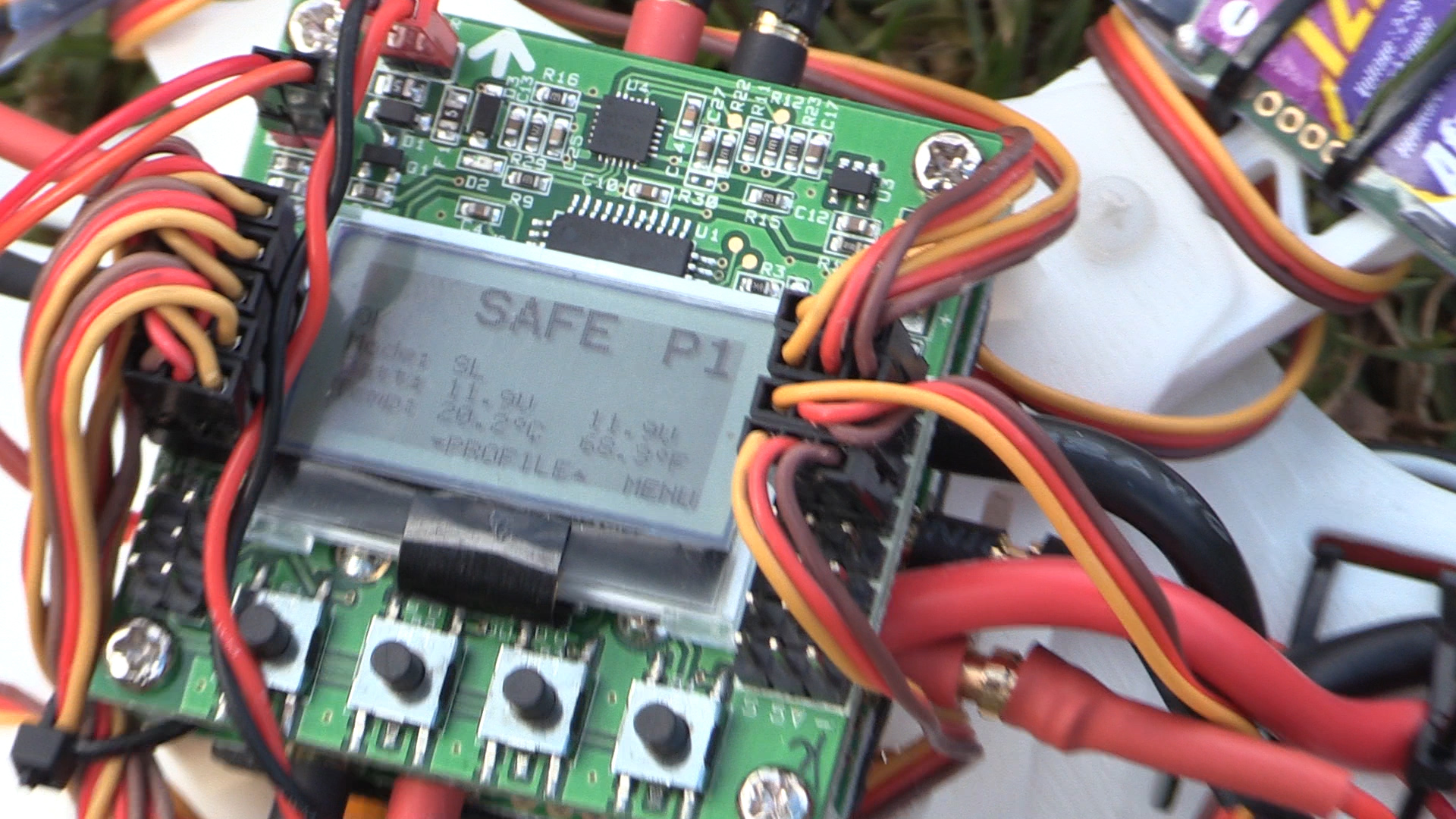
Eventually, I had everything connected and working.
I installed the largest propellers and took the quad outside to give it a shot. Unfortunately, it didn’t work – I applied the maximum thrust, all the propellers spun, loudly, the quadcopter wobbled on the ground – it wanted to take off, but just couldn’t.
This was annoying – now that everything was assembled and wired up it was disappointing for it not to work. Still, I knew that my mistake was in the choice of propellers, so I’d be able to get this sorted out.
I double-checked the specifications for my motors, came to the conclusion that 8″ propellers would give me the best mix of power and efficiency – and ordered a few different sets of 8″ propellers
A week went by, and the propellers arrived. Finally, I can get flying! I go to install the propellers, and- doh! They’re too big! What?
While I’d been excited that 8″ props would give me plenty of thrust, I’d forgotten to actually check that they’d fit – and while they do fit on the frame, they collide with one another. Whoops! That’s not going to work well (or at least, it’s not going to work well for very long…).
Novice mistake number two: not measuring that things will fit.
Determined not to waste any more time or money on new propellers, I decided I’d go for a simpler solution: let’s just make the frame bigger. The arms that hold the motors in place are already 3D printed, so let’s make those larger.
First, I needed to know exactly how long the new arms had to be. So I sat down and did what I should have done
Using SolidWorks, I did up a quick sketch to represent the four propellers.
Yes, they’re definitely colliding all right. Why didn’t I check this before…
Let’s say we increase the diagonal spacing to a nice round 300mm – would that get us out of trouble?
Yeah, it looks like that would do it. There’s a bit of clearance between each propeller, so even if things are a little out of place it should be okay.
So, knowing that the current arms provide the spacing of 250mm, all I had to do was extend each arm by 25mm. How hard could it be?
I already had SolidWorks open, so I sat down and went to work. I had soon drawn up a replacement arm that would be 25mm longer.
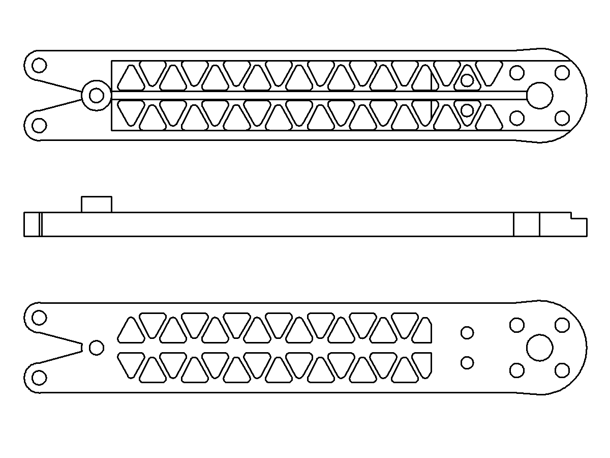
While I was at it, I made a few other modifications. I thickened the arm slightly to make it stronger, as I was worried the longer arm would be more prone to breaking. I shortened the vertical standoff that set the distance between the two plates at the centre of the quadcopter – I wasn’t putting anything inside of them, and shortening that distance would help with strength. I also added extra mounting holes near the motors, so that I could mount some sort of landing feet if I ever wanted to.
With the design done, I started printing the first of the new arms. Half an hour later, I had it in hand and was able to compare it with the old arm.
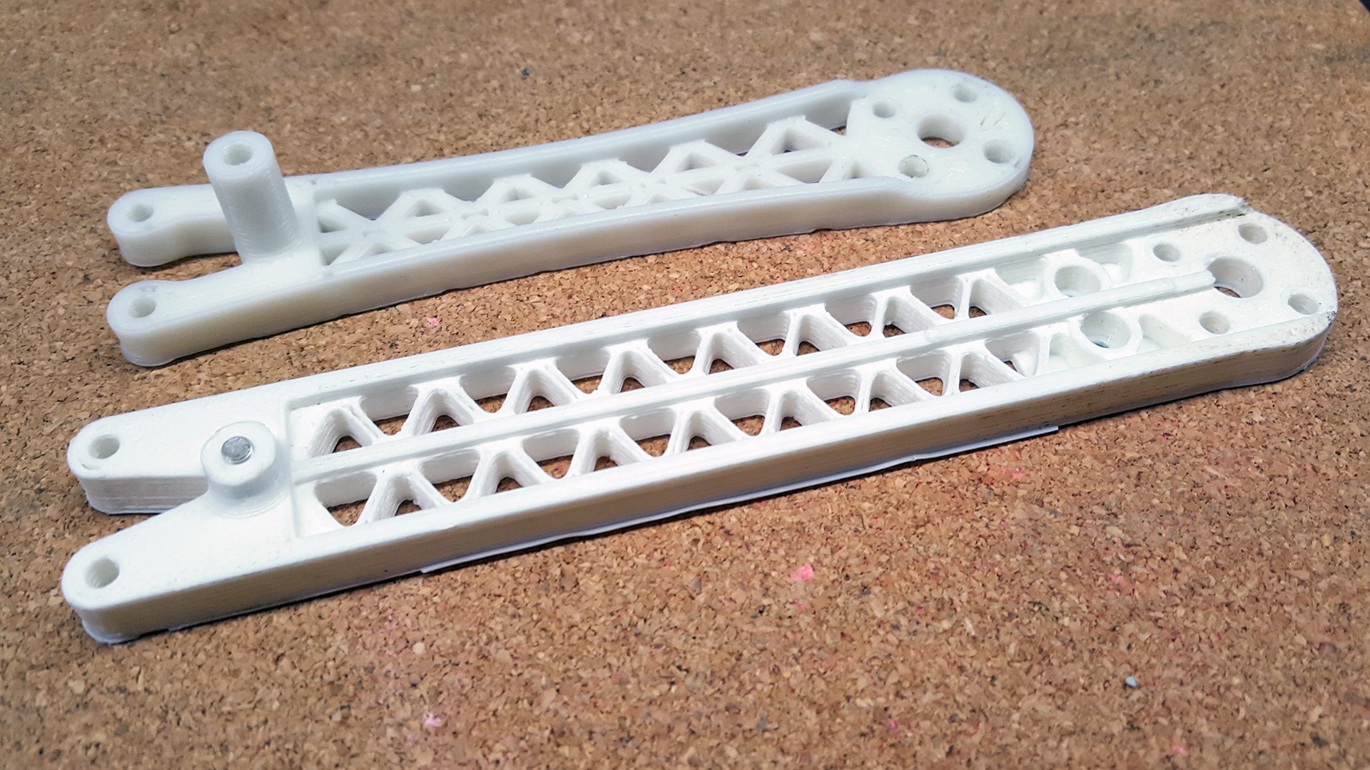
Happy that it would do the job, I started printing more. Soon, I had four arms installed and a spare set aside. Now, I was finally ready to give this a go!
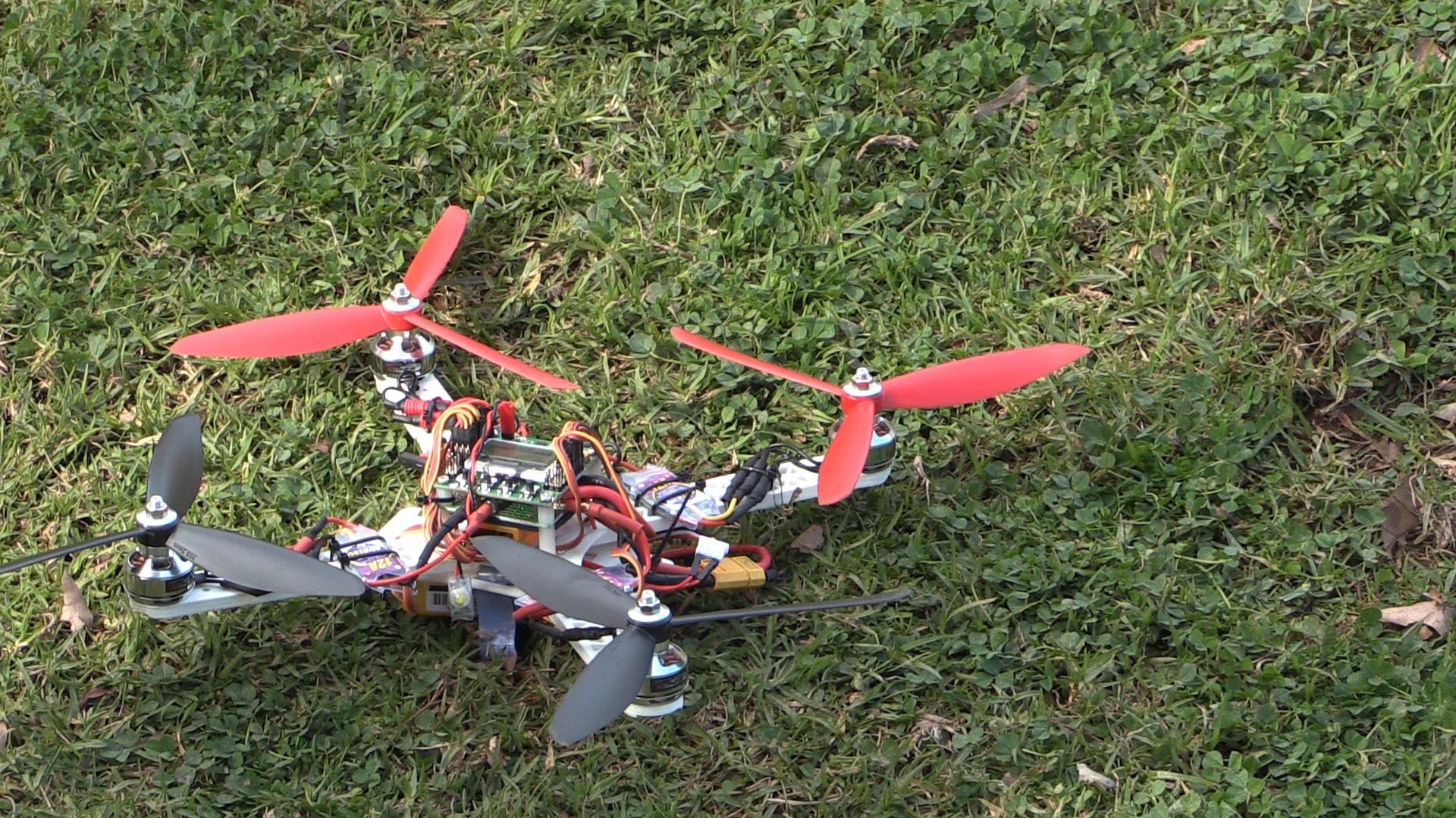
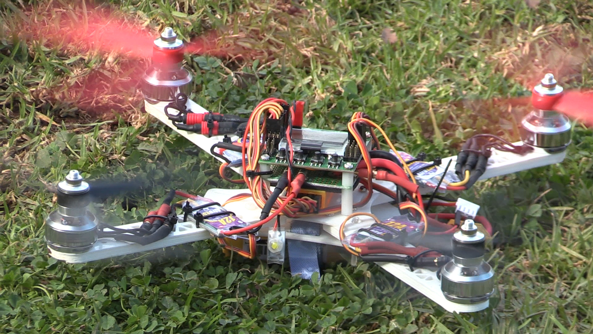

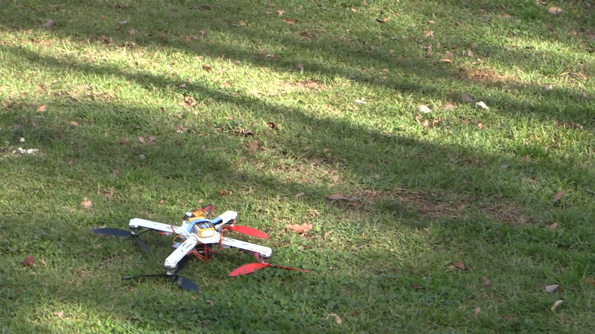
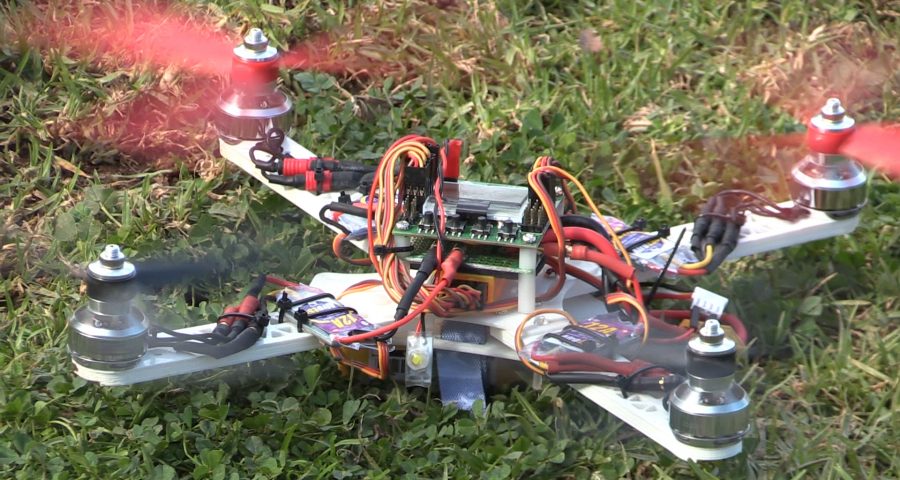
Crashes aside, it flies well! I have a lot to learn as a pilot (I’ve not done any RC flying before), but the quadcopter itself seems to work as intended.
The propellers tend to break or bend on every crash, so I’m going through a lot of those. The quadcopter itself is fairly sturdy, but I have snapped the arms a couple of times in very hard crashes. Maybe that’s something to try and improve in a future project?
I’m hoping to record video of it in action sometime soon, and will add it here when I do!
Leave a Reply